Possible perforation designs include:
Round ventilation holes
Longitudinal slots
Rectangular openings
Side-wall perforations
Connection holes
Cable fixing holes
Customized hole combinations
Main Technical Parameters
| Item |
Typical Specification |
| Product |
Perforated Cable Tray |
| Material |
Galvanized Steel / Stainless Steel |
| Thickness |
0.80–2.50 mm |
| Coil Width |
100–1250 mm |
| Tray Width |
50–1000 mm |
| Side Wall Height |
30–200 mm |
| Hole Diameter |
4–20 mm |
| Slot Length |
10–50 mm |
| Punching Speed |
According to Pattern |
| Forming Speed |
6–15 m/min |
| Forming Stations |
16–28 |
| Shaft Diameter |
70–90 mm |
| Main Motor |
15–30 kW |
| Cutting Method |
Hydraulic |
| Length Measurement |
Encoder |
| Control System |
PLC + HMI |
Hole Arrangement & Cable Fixing
The perforation pattern can be selected according to how the tray will be used after installation. Openings in the bottom can provide multiple positions for cable ties and clamps, while side-wall holes can be used for accessories or joining components.
The distance between holes is controlled through the feeding and punching system. For repeating patterns, servo feeding can coordinate material movement with the punching cycle, helping maintain the specified pitch throughout the production run.
When the tray requires different hole groups, the punching tooling can be arranged with multiple dies. This allows several openings to be processed during one punching cycle instead of producing each hole individually.
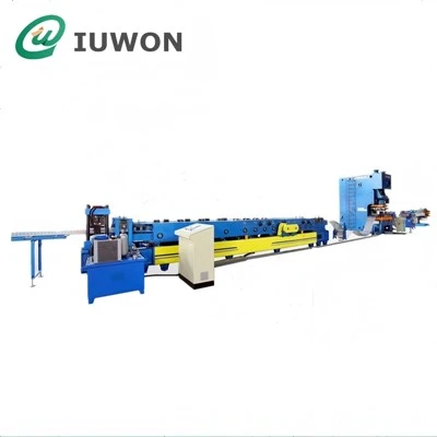
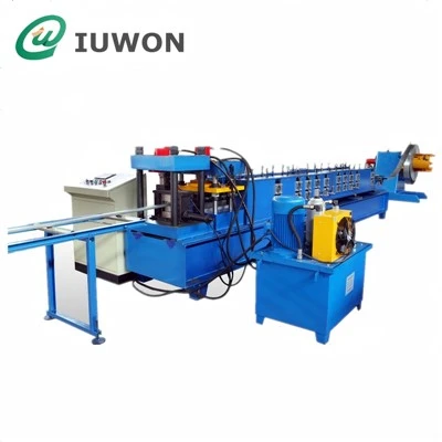
Punching & Forming Configuration
| Production Unit |
Available Option |
| Coil Decoiler |
Hydraulic |
| Coil Capacity |
3–10 Tons |
| Strip Leveling |
5–7 Roller |
| Feeding |
Servo / Gear Feeding |
| Punching System |
Hydraulic / Servo |
| Punching Dies |
Single / Multiple Stations |
| Hole Pattern |
Programmable |
| Roll Forming |
Dedicated Tray Tooling |
| Side-Wall Forming |
Multi-Pass |
| Reinforcement Beading |
Optional |
| Cut-Off |
Hydraulic |
| Measuring |
Encoder |
| Finished Product Support |
Conveyor / Run-Out Table |
| Stacking |
Optional Automatic Stacker |
Applications for Perforated Cable Trays
The completed trays provide an open cable-support route for electrical and communication systems. Their perforated structure makes it easier to attach cables and accessories while allowing air to circulate around the cable bundle.
Power Distribution
Perforated trays can be used to organize groups of electrical cables in factories, electrical rooms, substations, and utility facilities. Tray dimensions can be selected according to cable quantity and installation space.
Control & Instrumentation
Control cables and instrumentation wiring can be arranged inside narrower tray sections. The perforations provide convenient fixing points for separating and securing cable groups.
Communication Infrastructure
Open tray construction allows installers to access cables from above during installation and maintenance. This is useful in data, communication, and equipment areas where cable routing may change over time.
Industrial Facilities
Production plants and machinery areas often contain multiple cable routes running between equipment and electrical cabinets. Perforated trays provide a defined support path while keeping the wiring accessible.
Tray Section, Hole Pattern & Tooling Design
The forming tooling and punching equipment need to be considered together because the holes are created before the flat strip becomes the finished tray shape.
For example, a hole positioned near the edge of the flat strip may ultimately appear on the tray side wall. A hole closer to the centerline may become part of the tray bottom. The punching layout must therefore be established from the final three-dimensional section.
| Design Information |
Production Impact |
| Tray Width |
Determines material development |
| Side-Wall Height |
Determines forming geometry |
| Hole Position |
Determines punch location |
| Hole Diameter |
Determines punch and die |
| Slot Dimensions |
Determines punching tooling |
| Hole Pitch |
Determines feeding synchronization |
| Material Thickness |
Determines punching force |
| Tray Depth |
Influences roller arrangement |
| Reinforcement Ribs |
Require additional forming passes |
| Finished Length |
Determines cut-off program |
For high-volume production, the line can be configured with dedicated punching dies and roller tooling for frequently manufactured tray specifications. When a new perforation pattern is required, the punching tooling can be changed according to the new product drawing.
The result is a production line in which punching establishes the cable-management openings first, while roll forming subsequently converts the perforated strip into the final tray section. This coordinated sequence allows the hole pattern and tray geometry to remain consistent throughout continuous production.