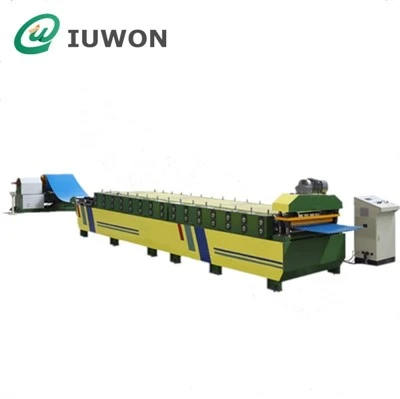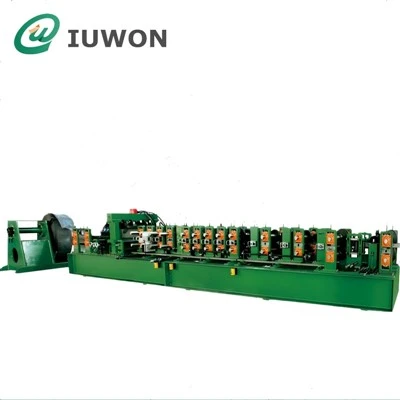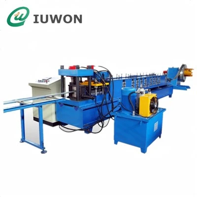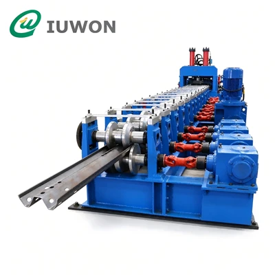

-
![Cable Tray Forming Machine]() Cable Tray Forming Machine
The cable tray roll forming machine is designed for the continuous production of cable management systems, including ladder trays, perforated trays, and solid-bottom trays. It processes metal...
-
![Cable Tray Ladder Roll Forming Machine]() Cable Tray Ladder Roll Forming Machine
A Cable Tray Ladder Roll Forming Machine is designed to manufacture metal side rails or ladder-type cable support profiles used in industrial cable routing systems. Depending on the product...
-
![Cable Tray Cover Roll Forming Machine]() Cable Tray Cover Roll Forming Machine
The Cable Tray Cover Roll Forming Machine is designed to produce metal covers for cable tray systems. It forms flat metal sheets into specified cover profiles through a series of rollers, creating...
-
![Heavy Duty Cable Tray Roll Fomer]() Heavy Duty Cable Tray Roll Fomer
The Heavy Duty Cable Tray Roll Former is designed for continuous cold forming of thicker steel sheets into cable tray profiles used for installations requiring a stronger tray structure. Compared...
-
![Cable Tray Roll Former]() Cable Tray Roll Former
The Cable Tray Roll Former is a cold roll forming system for converting continuous metal strip into cable tray sections with a specified cross-sectional shape. The equipment forms the flat sheet...
-
![Automatic Cable Tray Roll Forming Machine]() Automatic Cable Tray Roll Forming Machine
The Automatic Cable Tray Roll Forming Machine is designed to continuously form metal sheets into cable tray profiles through a series of precision roll forming stations. The machine integrates...
-
![Perforated Cable Tray Roll Former]() Perforated Cable Tray Roll Former
The Perforated Cable Tray Roll former is designed to produce cable tray profiles with regularly arranged ventilation and mounting holes. The line combines coil feeding, hole punching, roll...
-
![Metal Sheet Profile Roll Forming Machine]() Metal Sheet Profile Roll Forming Machine
A Metal Sheet Profile Roll Forming Machine continuously converts metal coil into shaped sheet profiles through a sequence of precision forming rolls. The equipment is suitable for production lines...
-
![Perforted Cable Tray Roll Forming Machine]() Perforted Cable Tray Roll Forming Machine
Our Perforated Cable Tray Roll Forming Machine is a professional fully automatic cold roll forming line specially built to manufacture perforated cable trays widely used for cable management and...
-
![Cable Tray Cold Roll Forming Machine]() Cable Tray Cold Roll Forming Machine
Our cable tray cold roll forming machine is a fully automated, high-efficiency industrial production line specially designed for manufacturing various types of metal cable trays, including solid...
-
![Perforated Cable Tray Forming Machine]() Perforated Cable Tray Forming Machine
The Perforated Cable Tray Forming Machine is designed to produce cable trays with regularly distributed openings across the bottom, side walls, or both areas of the tray. The equipment processes...
-
![Tray Forming Machine]() Tray Forming Machine
The Tray Forming Machine is a roll forming system developed for continuous production of metal cable tray profiles. It processes galvanized steel, stainless steel, or coated steel coil into formed...


Cable Tray Roll Forming Machine Technical Specifications
The machine configuration is determined by the customer's cable tray drawings, material specifications and production requirements. The following ranges represent typical engineering configurations for cable tray manufacturing.


Complete Line Parameters
| Item | Typical Specification |
| Machine Type | Cable Tray Roll Forming Machine |
| Production Mode | Continuous Roll Forming |
| Applicable Products | Ladder / Trough / Perforated / Solid Bottom / Heavy-Duty Cable Tray |
| Forming Material | Galvanized Steel / Carbon Steel / Stainless Steel |
| Material Yield Strength | Approx. 235–550 MPa |
| Material Thickness | 0.6–3.0 mm |
| Material Width | According to developed tray profile |
| Coil Weight | 3–10 Tons, customized |
| Decoiler Capacity | 5–10 Tons, customized |
| Decoiler Type | Hydraulic Expansion / Powered Decoiler |
| Leveling System | Multi-Roller Precision Leveler |
| Feeding Method | Servo Feeding |
| Punching System | Hydraulic / Mechanical / Servo Punching |
| Punching Accuracy | Typically ±0.5 mm, depending on system |
| Forming Stations | Approx. 12–24 stations |
| Forming Shaft Diameter | Approx. Ø50–90 mm |
| Shaft Material | High-Strength Alloy Steel |
| Roll Material | GCr15 / Cr12 / Cr12MoV or equivalent |
| Roll Hardness | Approx. HRC58–62 |
| Main Drive | Gearbox / Chain / Direct Drive |
| Forming Speed | Approx. 8–25 m/min |
| Cutting Method | Hydraulic / Servo Flying Cut-Off |
| Cutting Length | 2,000–6,000 mm or customized |
| Length Accuracy | Typically ±1 mm/m or according to configuration |
| Control System | PLC + HMI + Encoder |
| Servo System | Servo Motor + High-Resolution Encoder |
| Working Voltage | 380 V / 50 Hz / 3 Phase or customized |
| Installation Direction | According to factory layout |
| Automatic Stacking | Optional |
| Production Line Length | Approx. 20–40 m, depending on configuration |
Note: The actual machine specifications are calculated according to the tray profile, material grade, thickness, punching pattern and required production speed. Heavy-gauge profiles normally require a stronger forming system and may operate at a lower speed than light-gauge trays.
Cable Tray Product Parameters
The production capability is not defined only by machine dimensions. The finished tray geometry determines the forming sequence, roll tooling and punching configuration.
| Cable Tray Parameter | Typical Range |
| Tray Width | 50–1000 mm |
| Tray Side-Wall Height | 25–200 mm |
| Material Thickness | 0.6–3.0 mm |
| Tray Bottom Configuration | Solid / Perforated / Slotted |
| Side-Wall Configuration | Straight / Flanged / Reinforced |
| Flange Height | 10–50 mm, customized |
| Bend Radius | According to material and profile |
| Tray Section Length | 2–6 m typical |
| Hole Diameter | 5–30 mm, customized |
| Slot Width | 5–30 mm, customized |
| Slot Length | 10–100 mm, customized |
| Hole Pitch | 10–500 mm, customized |
| Hole Rows | 1–Multiple Rows |
| Hole Position | Bottom / Side Wall / Flange |
| Tray Profile | U / C / Ladder / Reinforced Profile |
| Surface Finish | Galvanized / Pre-Galvanized / Stainless Steel / Painted |
| Connection Type | Flanged / Bolted / Customized |
| Cover Compatibility | According to tray profile |
| Connector Compatibility | According to engineering drawing |
For a customized machine, the maximum width, maximum side-wall height and maximum material thickness should be evaluated together, because forming load increases significantly when wide, high and thick profiles are combined.
Punching System Parameters
For perforated cable trays, punching accuracy is one of the most important production parameters because the hole pattern must correspond with the final tray geometry.


| Punching Parameter | Typical Configuration |
| Punching Type | Hydraulic / Mechanical / Servo |
| Hole Shape | Round / Rectangular / Slot / Customized |
| Hole Diameter | Approx. 5–30 mm |
| Slot Width | Approx. 5–30 mm |
| Slot Length | Approx. 10–100 mm |
| Hole Pitch | Programmable |
| Punching Rows | 1–Multiple Rows |
| Punching Position | Bottom / Side / Flange |
| Feeding Control | Servo Motor |
| Position Feedback | Encoder |
| Punching Control | PLC + HMI |
| Die Material | Hardened Tool Steel |
| Die Changeover | Quick-Change / Dedicated Die |
| Punching Synchronization | Servo-Synchronized |
| Repeat Accuracy | Typically ±0.5 mm, depending on configuration |
| Customized Hole Pattern | Available |
The punching system can be programmed according to the required longitudinal pitch and transverse position. For repeated production, the PLC can store different punching recipes for different cable tray specifications.
Forming System Parameters
The roll forming section is designed according to the actual deformation sequence of the tray.
| Forming Parameter | Typical Configuration |
| Forming Stations | 12–24 |
| Shaft Diameter | Ø50–90 mm |
| Shaft Material | 40Cr / 42CrMo or equivalent |
| Roll Material | GCr15 / Cr12 / Cr12MoV |
| Roll Hardness | HRC58–62 |
| Roll Surface | Precision Machined |
| Guide System | Adjustable Entry Guides |
| Forming Direction | Progressive Multi-Pass Forming |
| Corner Formation | Multi-Pass Controlled Bending |
| Side-Wall Forming | Progressive Vertical Forming |
| Flange Forming | Dedicated Forming Passes |
| Profile Calibration | Adjustable |
| Straightening | Multi-Point Calibration |
| Drive System | Gearbox Transmission |
| Speed Control | Frequency Converter / Servo Control |
| Maximum Forming Speed | Approx. 8–25 m/min |
The number of forming passes is not selected simply according to machine size. A deeper tray, thicker material, smaller bend radius or reinforced flange generally requires a more carefully distributed forming sequence.
Cable Tray Production Process
The complete manufacturing process is organized specifically around long, thin-walled electrical cable tray production:
Galvanized / Steel Coil
↓
Hydraulic Decoiling
↓
Precision Leveling
↓
Servo Feeding
↓
Engineering Hole Punching
↓
Cable Tray Progressive Roll Forming
↓
Side-Wall & Flange Calibration
↓
Straightness Correction
↓
Servo Length Measurement
↓
Automatic Cutting
↓
Finished Tray Discharge
↓
Stacking
This arrangement allows the punching, forming and cutting operations to work as one coordinated system.
Why Cable Tray Manufacturing Requires Dedicated Process Control
Straightness of Long Tray Sections
A cable tray can be several meters long while its wall thickness may be only a few millimeters.
This high length-to-thickness ratio makes the product sensitive to residual coil stress, uneven forming forces and improper material guidance.
The line therefore incorporates leveling, controlled feeding, progressive forming and final calibration to reduce:
Longitudinal bow
Side bending
Profile twisting
Uneven tray opening
Side-wall deformation
For installation, consistent straightness is important because long tray sections need to align with supports and connectors.
Side-Wall Verticality
The side walls of a tray are not merely decorative features. Their geometry determines the actual tray width, cover fit, connector position and usable cable-routing space.
The forming sequence therefore needs to control the transition from the horizontal bottom to the vertical side wall.
For high side-wall profiles, additional forming passes may be required to prevent localized deformation.
Hole Position Synchronization
A perforated cable tray requires the hole pattern to remain correctly positioned relative to the tray centerline and side edges.
The control system can synchronize:
Encoder feedback → Material travel → Punching position → Forming length → Cutting position
This prevents the hole pattern from gradually drifting along long production runs.
Cable Tray Surface Protection
Galvanized and stainless-steel cable trays are frequently exposed in electrical installations, making surface quality an important part of the finished product.
The forming tooling can be engineered with:
Controlled roll geometry
Smooth material-contact surfaces
Proper entry guidance
Correct bend radii
Stable strip tracking
Reduced unnecessary sliding between material and tooling
The objective is to reduce scratches, zinc coating damage and localized surface marking during continuous production.
For pre-galvanized material, surface protection must be considered from coil entry through final forming rather than treated as a final inspection issue.
Cable Tray Product Categories
Ladder Cable Tray
Ladder cable tray consists of two longitudinal side rails connected by transverse rungs.
Its open structure provides cable accessibility and ventilation and is commonly used in power-intensive installations.
The production solution can be configured around:
Side-rail height
Tray width
Rung spacing
Rail flange geometry
Connection structure
Material thickness
Typical applications include power plants, substations, renewable energy facilities and large industrial electrical systems.
Trough Cable Tray
Trough cable trays provide continuous support beneath cables.
Compared with ladder structures, the forming process concentrates on maintaining the bottom surface and side-wall geometry.
Typical configurations include:
Solid-bottom tray
Flanged trough
Reinforced trough
Closed-edge tray
These profiles are commonly used in commercial buildings, municipal infrastructure and cable-management systems requiring greater cable support or protection.
Perforated Cable Tray
Perforated cable trays combine a formed tray profile with a repeated hole or slot pattern.
The machine can integrate punching before roll forming so that the flat strip receives the required pattern before being transformed into the final profile.
Typical controlled parameters include:
Hole size + hole pitch + row arrangement + edge distance + longitudinal position
This makes the system suitable for standardized electrical engineering production.
Heavy-Duty Cable Tray
Heavy-duty cable trays normally use thicker steel and reinforced profiles.
Typical material thickness can reach approximately 1.5–3.0 mm, depending on the required load-bearing structure.
The machine must therefore consider:
Higher forming force
Larger shaft diameter
Higher-strength roll tooling
Reinforced machine frame
Lower deformation per forming pass
Controlled production speed
This configuration is suitable for power stations, substations, industrial plants and energy infrastructure.
Multi-Profile Cable Tray Production
Cable tray manufacturers often need to produce multiple combinations of width and height rather than one fixed product.
A flexible production line can be designed around a defined profile family.
For example:
| Production Requirement | Configuration |
|---|---|
| Different Tray Widths | Adjustable / Interchangeable Tooling |
| Different Tray Heights | Adjustable / Interchangeable Tooling |
| Multiple Hole Patterns | Programmable Punching |
| Different Cutting Lengths | Servo Length Control |
| Different Materials | Recipe-Based Machine Setup |
| Multiple Tray Profiles | Dedicated Tooling / Quick Change |
| Mixed Orders | Stored PLC Production Recipes |
The appropriate changeover structure depends on how different the profiles are. Completely different tray geometries normally require dedicated tooling rather than simply changing machine parameters.
Cable Tray Roll Forming Machine for Electrical Infrastructure
Renewable Energy Projects
Cable tray systems are required for power collection, inverter connections, control cables and auxiliary electrical systems in:
Solar power plants
Battery energy storage facilities
Wind power projects
Renewable-energy substations
Large projects can require standardized tray sections in high volumes, making continuous roll forming suitable for repeat production.
Municipal Power Distribution
Urban power-grid construction requires cable management products for:
Distribution networks
Substations
Utility corridors
Electrical infrastructure upgrades
Underground power facilities
The production line can manufacture standardized tray profiles or customized sections according to project drawings.
Commercial Buildings
Commercial complexes, office buildings and industrial parks use cable trays for power distribution, communication and low-voltage systems.
Perforated and trough tray production lines can be configured for different cable capacities and installation spaces.
Industrial Power Systems
Factories, chemical facilities, metallurgical plants and other industrial environments often require heavy-duty or corrosion-resistant cable tray structures.
Material selection can include galvanized steel, stainless steel and other project-specified materials.
Rail Transit and Tunnel Projects
Metro systems, railway infrastructure and tunnels require cable management systems for:
Power supply
Signaling
Communication
Control systems
Auxiliary electrical equipment
Tray dimensions can be adapted to restricted installation spaces and project-specific support structures.
Cable Tray Roll Forming vs. Conventional Bending
Traditional Segmental Bending
Press-brake bending processes a sheet section by section.
For long cable trays, repeated positioning can introduce dimensional variations between sections and requires additional material handling.
A continuous roll forming line forms the profile progressively from coil material, which is more suitable for standardized long-section production.
Simple Cable Tray Machines
A basic machine may produce a simple tray profile, but a complete cable tray production line needs to coordinate:
Leveling + Punching + Forming + Calibration + Cutting
The production quality therefore depends on the complete process chain rather than only the forming rollers.
General Roll Forming Machines
General roll forming equipment can produce numerous metal profiles, but cable tray production has dedicated requirements involving:
Engineering hole patterns
Long-section straightness
Side-wall verticality
Connector compatibility
Cover compatibility
Galvanized surface protection
Multiple tray dimensions
Standardized cutting lengths
The machine is consequently designed around the actual cable tray profile rather than treated as a generic cold-forming machine.
Cable Tray Production Engineering
Our cable tray systems are developed from the finished product backward.
Cable Tray Drawing Analysis
The engineering team evaluates:
Finished width
Finished height
Developed width
Bend positions
Bend radius
Material thickness
Hole pattern
Hole pitch
Cutting length
Connection geometry
Roll Tooling Development
The forming passes are calculated according to the material's deformation characteristics and final profile requirements.
Punching Die Development
Punching dies are designed according to the actual hole dimensions and pattern rather than using a standard punching arrangement.
Line Configuration
The decoiler, leveler, feeder, punching unit, forming mill, cutting system and discharge table are matched according to the required production capacity.
Cable Tray Roll Forming Machine FAQ
Can the machine produce galvanized cable trays without scratching the coating?
Yes. The forming section can be configured specifically for pre-galvanized steel, with controlled material guidance, suitable roll geometry and stable strip tracking to reduce surface damage.
Can it produce stainless-steel cable trays?
Yes. Stainless steel can be processed, but the tooling and forming parameters should be selected according to the stainless-steel grade and thickness because its forming behavior differs from galvanized carbon steel.
What material thickness can the machine process?
A typical configuration covers approximately 0.6–3.0 mm. The actual maximum thickness depends on material strength, tray width, side-wall height and profile geometry.
What cable tray width can be produced?
Typical production can cover approximately 50–1000 mm, subject to the developed width, material thickness and machine configuration.
Can the punching pattern be customized?
Yes. Hole size, hole shape, hole pitch, number of rows, edge distance and longitudinal spacing can all be designed according to the customer's cable tray drawing.
Can one machine produce multiple cable tray sizes?
Yes, within a defined profile family. Adjustable tooling, interchangeable tooling or quick-change configurations can be selected according to the required product range.
Can one line produce ladder and perforated cable trays?
This depends on the actual product designs. Ladder trays and perforated trays have different forming structures, so they may require different tooling or separate forming sections. The production solution should be determined after reviewing the actual drawings.
How is cable tray dimensional accuracy controlled?
Accuracy is controlled through material leveling, stable servo feeding, precision roll tooling, progressive forming, profile calibration, encoder feedback and servo-controlled cutting.
How is hole positioning controlled?
The punching system uses programmed feeding distances and encoder feedback to synchronize the punching position with the actual material travel.
Can the machine produce heavy-duty cable trays?
Yes. Heavy-duty configurations can be designed for thicker materials and reinforced tray profiles. The machine frame, shafts, tooling and transmission system are selected according to the required forming load.
Cable Tray Roll Forming Machine: Designed Around Electrical Engineering Requirements
Cable tray manufacturing requires a production system that controls more than the basic cross-sectional shape.
The complete process must maintain:
Dimensional consistency → Hole-position accuracy → Side-wall geometry → Longitudinal straightness → Surface integrity → Cutting accuracy
Our Cable Tray Roll Forming Machine solutions cover the complete production requirements for:
Ladder Cable Trays
Trough Cable Trays
Perforated Cable Trays
Solid-Bottom Cable Trays
Heavy-Duty Cable Trays
Multi-Profile Cable Tray Production
From coil processing and engineering-hole punching to progressive forming, profile calibration and servo cutting, each production line is configured according to the customer's actual cable tray profile, material and production requirements.
Send your cable tray drawings, material thickness, tray dimensions and required hole patterns to develop a production-line configuration matched to your electrical cable tray manufacturing requirements.
Hangzhou IUWON Technology Co., Ltd. is one of the most professional cable tray roll forming machine manufacturers and suppliers in China. Please feel free to buy custom made cable tray roll forming machine made in China here from our factory. For price consultation, contact us.
Cable Tray Former, cable tray machine, cable tray roll forming machine