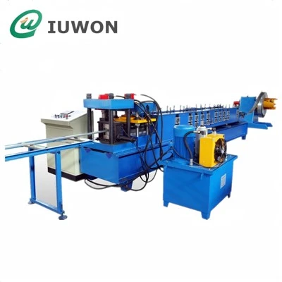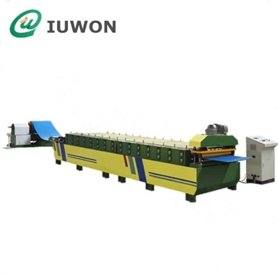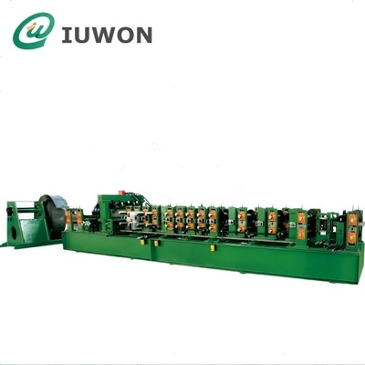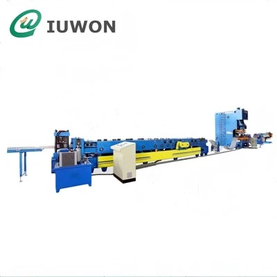

Hangzhou IUWON Technology Co., Ltd. is one of the most reliable manufacturers and suppliers of cable tray making machine in China. With abundant experience, we warmly welcome you to buy high quality cable tray making machine from our factory. Good service and reasonable price are available.
Tray Structure & Load-Carrying Geometry
Cable tray dimensions are determined not only by overall width but also by the relationship between the bottom panel and side walls. Deeper side walls can increase the section's resistance to bending, while ribs, beads, or folded edges can further reinforce the tray without requiring excessive material thickness.
The forming system can produce different tray constructions, including:
Perforated cable trays
Solid-bottom trays
Ladder-type tray components
Slotted cable trays
Raceway sections
Heavy-duty cable trays
Cable tray side rails and covers
For perforated designs, holes can be produced at predefined intervals before or during the forming process. The punching pattern can be selected according to cable fixing requirements, ventilation needs, and connection hardware.

Cable Tray Machine Parameters
| Parameter | Typical Specification |
|---|---|
| Material | Galvanized Steel / Stainless Steel / Pre-Painted Steel |
| Material Thickness | 0.80–3.00 mm |
| Tray Width | 50–800 mm |
| Side Wall Height | 30–150 mm |
| Coil Width | According to Tray Size |
| Forming Speed | 6–18 m/min |
| Forming Stations | 14–24 |
| Shaft Diameter | 70–90 mm |
| Shaft Material | 40Cr |
| Roller Material | GCr15 / 45# Steel |
| Main Motor | 11–30 kW |
| Transmission | Gearbox |
| Punching | Hydraulic / Servo |
| Cutting | Hydraulic Cut-Off |
| Length Control | Encoder + PLC |
| Control System | PLC + Touchscreen |
| Power Supply | 380 V / 50 Hz / 3 Phase |
Perforation & Connection Preparation
Many cable tray systems use perforated bottoms or side walls. These openings reduce material weight, improve ventilation, and provide multiple points for cable ties and fixing accessories.
The punching unit can be selected according to the tray's hole shape and spacing. Round holes, elongated slots, and customized openings can be incorporated into the production program. For high-volume production, servo-controlled punching provides synchronized positioning between the hole pattern and the tray length.
Connection areas can also be prepared during production where the tray design requires regularly spaced joining holes. This reduces the amount of drilling required during installation and allows sections to be connected using standard tray hardware.
Production Line Configuration
| Section | Available Configuration |
| Decoiler | Manual / Hydraulic |
| Coil Capacity | 3–8 Tons |
| Leveling | 5–7 Roller Unit |
| Entry Alignment | Adjustable Guide System |
| Punching | Servo / Hydraulic |
| Hole Pattern | Programmable |
| Forming Unit | Customized Tray Tooling |
| Reinforcement Beading | Optional |
| Cutting | Stop / Flying Cut-Off |
| Measuring | Encoder |
| Drive | Gearbox Transmission |
| Discharge | Run-Out Conveyor |
| Control | PLC + HMI |
| Tray Cover Tooling | Optional Separate Tool Set |
Applications in Cable Management Systems
The finished trays are installed on walls, ceilings, floors, cable bridges, equipment structures, and support frames to organize and protect cable routes.
Typical applications include:
Industrial Plants
Used for power distribution, instrumentation, automation, and control cables around production equipment.
Commercial Buildings
Cable trays provide organized routes for electrical and communication wiring in offices, shopping centers, and large buildings.
Data & Communication Facilities
Perforated and ventilated tray sections can be used for structured cabling and communication infrastructure.
Power Infrastructure
Heavy-duty tray sections can carry larger groups of power cables in substations, utility facilities, and electrical rooms.
Infrastructure Projects
Cable management systems are also used in tunnels, transportation facilities, airports, and other large installations.
The tray configuration can be selected according to cable quantity, cable weight, support spacing, environmental conditions, and available installation space. Width and side-wall height can therefore vary substantially between projects.
Tray Design & Production Options
Different cable management systems require different tray constructions. A light-duty communication installation may use a narrow perforated tray, while power installations can require thicker steel, deeper side walls, and reinforced bottom sections.
The machine can be designed around the required tray geometry, with the following factors determining the final configuration:
| Design Requirement | Machine Consideration |
| Tray Width | Roller working width |
| Side-Wall Height | Forming pass arrangement |
| Material Thickness | Forming force |
| Load Requirement | Reinforcement geometry |
| Hole Shape | Punching die |
| Hole Pitch | Punching control |
| Tray Length | Cut-off programming |
| Joint Design | Connection-hole arrangement |
| Surface Treatment | Material and roller selection |
| Production Volume | Line-speed configuration |
For galvanized cable trays, the forming tooling can be finished to reduce unnecessary surface damage. For stainless steel or heavier materials, the machine structure and drive system can be selected according to the additional forming load.
The line can also be arranged to produce several tray sizes with dedicated tooling sets, allowing manufacturers to maintain separate profile geometries for light-duty, medium-duty, and heavy-duty cable management applications.
Hot Tags: cable tray making machine, China cable tray making machine manufacturers, suppliers, factory, Cable Tray Forming Machine, cable tray machine, cable tray roll forming machine, cable tray section roll forming line, industrial cable tray forming machine, ladder type cable tray forming machine