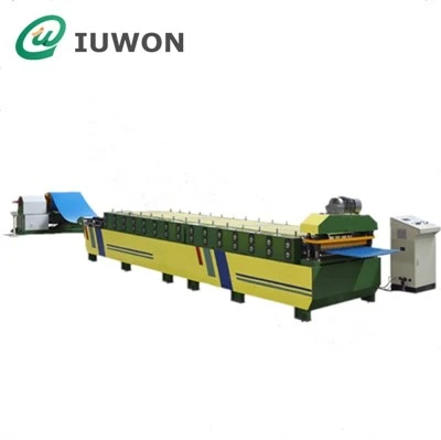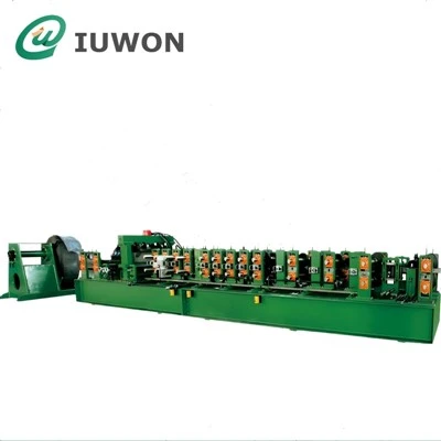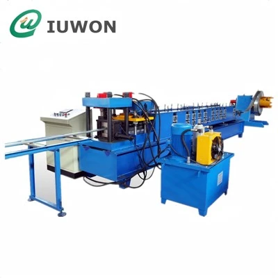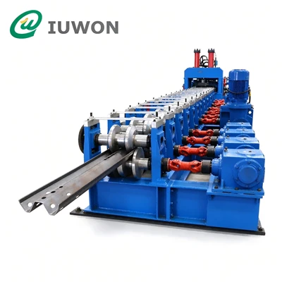
A cable tray cover roll forming machine converts metal coil into a continuous cover profile through a series of forming stations. The finished section may have flat or slightly crowned surfaces, folded edges, return lips, or other shapes specified by the customer's drawing.
The purchasing decision depends on more than the nominal cover width. A cover measuring 200 mm across the top, for example, may require a different developed strip width and roller arrangement from another 200 mm cover with deeper side flanges or inward-folded edges.
Before selecting equipment, buyers should clarify:
- The exact cross-sectional drawing of each cover.
- The finished width, side height, and edge geometry.
- The material grade, thickness, and coating condition.
- The required cover lengths and dimensional tolerances.
- Whether multiple profiles must be produced on one line.
- The required output per shift and the available factory space.
These details establish the engineering basis for a custom production line and help prevent tooling changes after manufacturing has started.
Preliminary Technical Parameters for Custom Production
The following figures are illustrative engineering reference ranges for initial discussions only. They are not confirmed specifications for a particular IUWON machine. Actual parameters must be established from approved profile drawings, material properties, and the required production cycle.
|
Technical Item |
Preliminary Reference Range or Option |
Confirmation Required |
|---|---|---|
|
Product type |
Flat, folded-edge, return-lip, or custom cover |
Approved cross-sectional drawing |
|
Material |
Galvanized steel, cold-rolled steel, or other specified coil |
Material grade and surface condition |
|
Material thickness |
Approximately 0.5–1.5 mm |
Minimum and maximum thickness and yield strength |
|
Finished cover width |
Project-dependent; approximately 50–600 mm as a broad initial reference |
Finished dimensions and developed strip width |
|
Side flange height |
Drawing-dependent; approximately 10–50 mm for preliminary discussion |
Flange dimensions and bend geometry |
|
Forming stations |
Approximately 10–18 as an initial reference |
Roller design and required profile complexity |
|
Forming speed |
Approximately 8–20 m/min as a preliminary discussion range |
Actual speed with the specified material and profile |
|
Cutting method |
Hydraulic fixed-length cutting or another suitable arrangement |
Cut geometry, length range, and edge quality |
|
Length tolerance |
To be specified against the approved drawing; ±1 mm per 3,000 mm may be discussed as a preliminary target |
Contractual tolerance and measurement method |
|
Width adjustment |
Fixed tooling, manual adjustment, or motorized adjustment |
Number of sizes and expected changeover frequency |
|
Control system |
PLC with operator interface |
Length setting, batch control, and saved production settings |
|
Finished product handling |
Run-out table or optional stacking arrangement |
Cover length, bundle size, and handling method |
All numerical values are preliminary references, not guaranteed machine capabilities. The supplier should confirm the applicable range for each component and state the final agreed specifications in the technical proposal.
The most important point is to distinguish finished cover width from coil strip width. The required strip width depends on the cross-sectional geometry and the material consumed by the bends. It should be calculated from the approved drawing rather than selected from the finished width alone.
Why Custom Cover Geometry Matters
Cable tray covers may look simple because they generally have fewer bends than the tray body. However, small changes to the edge design can affect fit, stiffness, handling, and the suitability of the forming tooling.
A flat cover with simple folded edges may require a relatively straightforward forming sequence. The main considerations are maintaining a consistent width, forming the edges without twisting the panel, and keeping the finished cover flat enough to sit correctly on the tray.
If the cover is too wide, it may not engage correctly with the tray edges. If it is too narrow, it may leave gaps or fail to stay in position.
Some covers use inward- or outward-folded edges to improve retention or create a particular installation interface. These bends must match the mating tray profile.
The roller design must account for bend depth, material thickness, springback, and the sequence in which the edges are formed. A profile with multiple narrow bends may need a different forming sequence from a cover with two simple side flanges.
Certain projects require nonstandard widths, different side heights, special edge returns, or a particular appearance. In these cases, the buyer should provide the complete cross-sectional drawing, not just a photograph of the finished product.
The drawing should identify all critical dimensions, bend directions, corner radii where applicable, and tolerances. If the cover must fit an existing tray system, providing the mating tray drawing can help verify the interface before tooling is manufactured.
Purchasing recommendation: Approve the cover drawing and its relationship to the tray before confirming the roller tooling. This reduces the risk of receiving equipment that forms a visually similar but incompatible profile.
Match the Machine to the Required Steel Coil
Material selection affects forming load, springback, surface appearance, and the risk of edge cracking or deformation. Buyers should therefore define the raw material specification before requesting a final quotation.
|
Material Consideration |
Why It Affects Machine Selection |
|---|---|
|
Steel grade and yield strength |
Higher-strength material can require different forming forces and tooling design. |
|
Thickness range |
Determines the load on rollers, shafts, drive components, and cutting equipment. |
|
Coil width |
Must match the developed strip width and feeding arrangement. |
|
Coil weight and inside diameter |
Determine decoiler capacity and material-handling requirements. |
|
Galvanized or coated surface |
Influences roll-contact conditions and surface-protection requirements. |
|
Incoming flatness |
Affects feeding stability and finished-cover straightness. |
|
Material consistency |
Variations can affect dimensional repeatability and springback. |
The decoiler must accommodate the specified coil weight and dimensions. The feeding and guiding system must keep the strip aligned as it enters the forming section.
The roller stations must progressively produce the specified bends without introducing unwanted twist, camber, or surface damage. The cutting unit must then separate the finished cover without excessively deforming its edges.
If buyers intend to process several material grades or thicknesses, the supplier should confirm which adjustments are required between material types. A machine's ability to process one thickness does not automatically mean it can maintain the same speed and tolerances throughout a wider thickness range.
For pre-galvanized or pre-coated steel, scratches and pressure marks can affect the appearance and corrosion protection of the finished product. Buyers should discuss roller surface condition, material guiding, contact pressure, and handling practices.
If the product requires post-forming coating or another finishing process, clarify whether that process is included in the production scope or handled separately.
Choose the Right Width-Adjustment and Changeover Method
Custom cover production often involves multiple widths and edge configurations. The best adjustment system depends on how many sizes are ordered, how frequently the factory changes products, and how different the cross-sections are.
Dedicated tooling is suitable when the factory produces one or a small number of stable, high-volume profiles. The setup is relatively straightforward, but introducing a new width or edge shape may require additional rollers or tooling modifications.
Buyers should confirm the cost and delivery time for future profile changes before purchasing a fixed configuration.
An adjustable forming arrangement can reduce the need to replace tooling for certain width changes. However, adjustment may require manual repositioning, measurement, alignment, and trial production.
Ask which dimensions can be adjusted and which profile features remain fixed. A width-adjustable system should not be assumed capable of forming every edge shape with the same tooling.
Motorized adjustment may be useful when the factory changes sizes frequently. Depending on the machine design, the operator may select a saved product setting and adjust specified components through the control system.
Before paying for this option, verify:
- Which dimensions are automatically adjusted.
- Which adjustments still require manual work.
- Whether different edge profiles need separate tooling.
- How the machine verifies the selected setting.
- How long a typical changeover takes under agreed conditions.
- Whether the new size requires trial pieces and dimensional correction.
The key commercial measure is not simply whether a machine is described as adjustable. It is the time, labor, tooling cost, and material waste required to change from one approved product to another.
Choose the Right Width-Adjustment and Changeover Method
Custom cover production often involves multiple widths and edge configurations. The best adjustment system depends on how many sizes are ordered, how frequently the factory changes products, and how different the cross-sections are.
Fixed-Profile Tooling
Dedicated tooling is suitable when the factory produces one or a small number of stable, high-volume profiles. The setup is relatively straightforward, but introducing a new width or edge shape may require additional rollers or tooling modifications.
Buyers should confirm the cost and delivery time for future profile changes before purchasing a fixed configuration.
Manually Adjustable Tooling
An adjustable forming arrangement can reduce the need to replace tooling for certain width changes. However, adjustment may require manual repositioning, measurement, alignment, and trial production.
Ask which dimensions can be adjusted and which profile features remain fixed. A width-adjustable system should not be assumed capable of forming every edge shape with the same tooling.
Motorized or Recipe-Based Adjustment
Motorized adjustment may be useful when the factory changes sizes frequently. Depending on the machine design, the operator may select a saved product setting and adjust specified components through the control system.
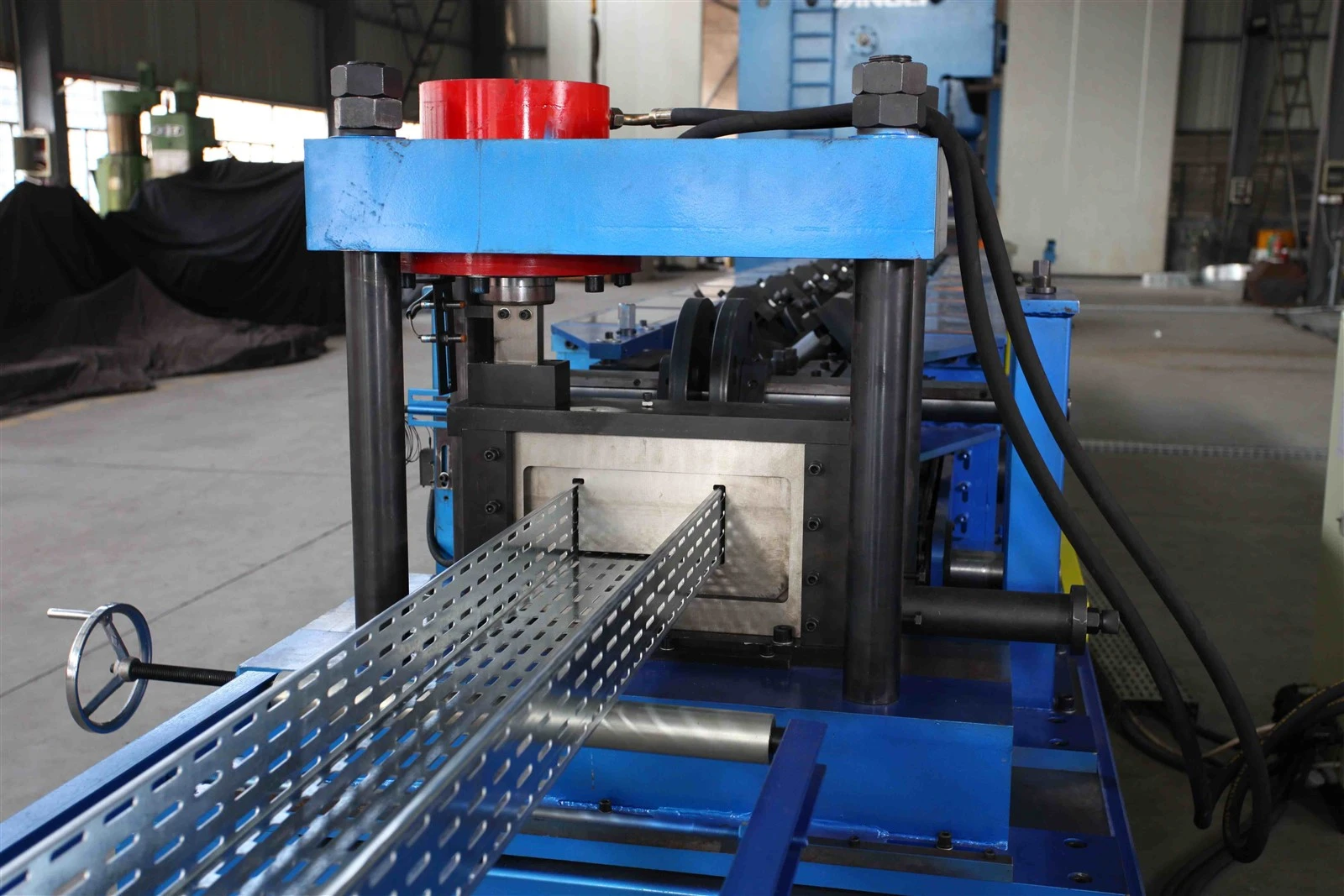
Evaluate the Forming Stations and Roller Design
Roll forming gradually bends the strip through multiple stations until the required cross-section is achieved. The number of stations alone does not determine the quality of the finished cover.
A suitable forming sequence should distribute deformation across the stations while controlling edge movement and maintaining the required geometry. Complex return lips or deeper flanges may require a different sequence from simple edge folds.
When reviewing the forming section, buyers should ask about:
- Frame rigidity under the intended forming load.
- Roller material, heat treatment, and surface finish.
- Shaft dimensions and bearing arrangement.
- Roller alignment and adjustment procedures.
- Drive transmission and maintenance access.
- Tooling design for the approved cross-section.
- Inspection methods for finished width, flange height, and straightness.
A cover may have the correct overall width but still fail to fit if its side flanges are uneven, its bends are inconsistent, or the panel is twisted.
The supplier should explain how the finished profile will be measured against the approved drawing. Depending on the product, inspection may include overall width, side height, bend angles, flatness, straightness, twist, and the fit between the cover and the corresponding tray.
The buyer should also agree on the sampling method. Measuring one sample during initial setup is not sufficient to demonstrate dimensional consistency throughout a production run.
Cutting Accuracy and Finished Length Control
Cable tray covers are commonly produced in specified lengths to suit transport, installation, and project requirements. Cutting performance influences both the finished dimension and the appearance of the panel ends.
A fixed-length cutting arrangement may suit a defined production cycle. Other cutting methods can be considered according to the material thickness, profile geometry, line speed, and required output.
Before selecting the cutting unit, confirm:
- The minimum and maximum finished lengths.
- The agreed length tolerance.
- Whether the cover can be cut without distorting its formed edges.
- The cutting method and tool arrangement.
- The control method for repeated batch lengths.
- The expected burr and end-condition requirements.
- Whether the cutting tools are included in the quotation.
For long covers, handling after cutting also matters. Poor support can cause bending or surface damage even when the cutting unit performs correctly. The run-out arrangement should therefore support the actual panel length and provide adequate space for safe collection and stacking.
Suppose a factory requires 2,400 covers during an 8-hour shift. The average required output is:
2,400 ÷ 8 = 300 covers per hour, or 5 covers per minute.
This is a planning calculation, not a machine performance guarantee. Actual output depends on cover length, forming speed, cutting cycle, product changes, material loading, and downstream handling.
Ask the supplier to estimate output using the intended product mix and operating conditions. A speed figure expressed only in meters per minute cannot be compared directly with a requirement expressed in finished covers per hour without accounting for panel length and production interruptions.
Decide Whether Punching Is Required
Unlike many cable tray bodies, a basic cover may not require a large number of punched holes. Some covers, however, use fixing holes, locking features, ventilation openings, or other specified details.
The buyer should determine whether these features are part of the cover profile and whether they need to be produced inline.
If punching is required, the machine design must address the hole shape, spacing, position, and relationship to the finished panel length. The supplier should also explain whether punching occurs before forming or through another suitable process.
For projects with several hole patterns, confirm whether the line requires additional dies, a separate punching station, or a changeover procedure.
If no punching is required, avoid paying for a punching system that does not contribute to the intended production process. A simpler configuration may reduce initial investment, maintenance needs, and setup complexity.
Compare the Complete Line Configuration
A cable tray cover production line may include a decoiler, feeding and guiding equipment, roll forming stations, a cutting unit, a control system, and a finished-product collection arrangement. Leveling, punching, powered decoiling, and automatic stacking can be included when required by the material and production target.
The final equipment scope should match the intended process.
|
Line Component |
Buyer Should Confirm |
|---|---|
|
Decoiler |
Coil weight, inside diameter, width, and loading method |
|
Feeding and guiding |
Strip alignment and compatibility with the required width |
|
Leveling unit, if required |
Suitability for the material and thickness |
|
Roll forming section |
Approved profile, roller tooling, and adjustment method |
|
Punching unit, if required |
Hole layout, die scope, and production cycle |
|
Cutting unit |
Length range, cutting method, and tolerance |
|
PLC and operator interface |
Length setting, batch quantity, alarms, and product recipes |
|
Run-out and collection |
Panel support, handling space, and stacking method |
|
Safety and maintenance provisions |
Guards, emergency stops, access, and servicing requirements |
Buyers should also verify the factory's electrical supply, compressed-air requirements if applicable, line footprint, maintenance access, and coil-handling facilities.
A line that fits the production drawing but cannot be installed safely in the available factory space may create additional civil work or layout changes. These practical factors should be reviewed before the order is confirmed.
Define Acceptance Testing Before Ordering
Machine acceptance should be based on measurable production results rather than a demonstration that the rollers rotate and the control system powers on.
Before manufacturing begins, agree on the test material, profile drawing, finished length, dimensional tolerances, operating conditions, and documentation required for acceptance.
A practical factory acceptance test may include:
- Checking the machine configuration against the approved quotation.
- Verifying control functions and safety devices.
- Running the specified material through the complete process.
- Producing covers at the agreed dimensions and lengths.
- Measuring the finished cross-section and edge geometry.
- Inspecting flatness, straightness, twist, and surface condition.
- Checking cut length and edge condition.
- Recording the operating speed and actual output under the agreed test conditions.
- Documenting deviations and corrective actions.
If the machine must produce several profiles, identify which sizes will be included in the test and whether changeover performance is part of the acceptance criteria.
The contract should define the measurement method and acceptance tolerances. Phrases such as "high precision" or "fast changeover" are not substitutes for specific, testable requirements.
Understand the Total Cost of Custom Profile Production
The initial equipment price is only one part of the investment. Custom cover production may also involve tooling, spare parts, material handling, installation, operator training, and future profile modifications.
When comparing proposals, consider the following cost factors:
- Initial machine configuration and included auxiliary equipment.
- Roller tooling for each approved profile.
- Additional dies for optional punching patterns.
- Manual labor required for loading, adjustment, cutting, and stacking.
- Material waste during initial setup and size changes.
- Maintenance requirements and replacement tooling.
- Installation, commissioning, and training.
- The cost and lead time of introducing new profiles later.
For a factory producing a narrow range of covers in large batches, dedicated tooling may be commercially sensible. For a factory supplying many customers with different widths and edge designs, an adjustable configuration may justify a higher initial investment if it reduces changeover time and tooling expenditure.
The correct comparison is the total cost of producing the required accepted covers over the expected operating period, not just the purchase price of the machine.
Information Buyers Should Send for a Quotation
A complete technical brief helps the equipment supplier assess the profile, select an appropriate forming sequence, and identify any optional equipment.
Prepare the following information where available:
- Profile drawings: Cross-sectional dimensions, bends, return lips, and critical tolerances.
- Finished dimensions: Cover width, flange height, length range, and end requirements.
- Raw material: Steel grade, thickness, yield strength, coating, and coil dimensions.
- Product variants: Number of widths, edge designs, and material specifications.
- Production target: Required covers per shift and typical batch size.
- Punching requirements: Hole shapes, locations, and patterns, if applicable.
- Changeover expectations: Whether sizes are changed daily, weekly, or only occasionally.
- Factory conditions: Floor space, electrical supply, lifting facilities, and operator arrangements.
- Acceptance requirements: Dimensional tolerances, test material, inspection records, and trial-production expectations.
- Project schedule: Required delivery, installation, and commissioning dates.
If the drawing is still under development, provide the preliminary dimensions and identify which features remain open. These can be reviewed during engineering before the tooling design is frozen.
Frequently Asked Questions
It depends on the forming structure and tooling design. Some machines use dedicated tooling for each profile, while others offer adjustable width settings or interchangeable tooling. Buyers should confirm the adjustable dimensions, required tooling changes, and actual changeover procedure.
The correct range depends on the cover drawing, steel grade, and project requirements. A preliminary range such as 0.5–1.5 mm can support initial discussions, but the final machine specification must be confirmed against the actual material and profile.
No. If the cover has no punched holes or other features requiring inline punching, the unit may not be necessary. Where fixing holes or special features are required, the supplier should assess their position, pattern, and effect on the production cycle.
It can be valuable when the factory frequently switches between multiple cover sizes. Its commercial value depends on how much manual work and downtime it saves, which profile dimensions it can adjust, and whether separate tooling is still needed for different edge shapes.
The factory acceptance test should verify the agreed machine configuration and produce samples from the specified material. Finished width, flange geometry, length, straightness, surface condition, cutting quality, and any required hole pattern should be checked against the approved criteria.
Conclusion: Build the Line Around the Approved Cover Drawing
A cable tray cover roll forming machine should be selected according to the actual cover geometry, raw material, required production output, and product-changeover plan. Although covers often have a simpler cross-section than cable tray bodies, their edge design and dimensional fit still determine whether they can be installed correctly.
Buyers should approve the cross-sectional drawing first, confirm the material range, and establish measurable acceptance criteria before comparing quotations. They should also decide whether fixed tooling or an adjustable configuration better matches the factory's product mix and order frequency.
IUWON can review your cover drawings, steel specifications, required lengths, and production target to help define a suitable equipment configuration. With the key technical information established at the quotation stage, buyers can compare machine scope, tooling investment, output expectations, and future customization requirements on a consistent basis.
For a quotation, prepare your cover profile drawing, material thickness range, finished width and length, required output, and number of profile variants. These details provide the starting point for an engineering review and a more accurate technical proposal.
SEO Title: Cable Tray Cover Roll Forming Machine for Custom Profiles
Meta Description: Find out how to select a cable tray cover roll forming machine for custom profiles, including material compatibility, edge forming, width adjustment, cutting accuracy, and production planning.
URL Slug: cable-tray-cover-roll-forming-machine-custom-profiles